PETROL TANK
PETROL TANK.
Harley
883 Iron


In a team of 9 we chose to work on the Harley 883 Iron fuel tank.
To get started we took multiple photos of the tank, in
multiple angles, in Photogrammetry; a software which takes multiple photos of
objects and sticking them together to create a 3D model of the object.
After this stage the finished Recap is then exported in STL
file format and uploaded into Fusion 360 slicer to prepare the fuel tank
template patterns to be cut. These patterns are classified in X and Y axis to
make it easy to slot them into place (making the template model)
Using a laser cutting machine we cut out the model template
patterns (3mm thick plywood) and all its components at a scale of 1:1 after
previewing the model and making sure all the sizes/shape and scale are correct
before proceeding to cut. You don’t want to make a mistake before cutting
because it takes a long time for the laser cutter to cut all the pieces and
also since it’s a big class and not enough laser cutters, and the need to book
the machines you’re better off doing it correct at once.
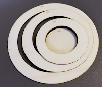
After cutting the template pieces/components we assembled
the model.

Fig.1. Assembled models
And then after the assembling process is complete we glued the model together
using a hot glue gun. Followed by taping the model (after the glue dried) with
masking tape but didn’t complete that process because it would have taken a lot
of time… and a lot of tape (considerate of our resources as you can see).

Fig.2. Gluing the Model components together to avoid falling apart
So to overcome this we cut straight to the chase.
We taped A2 paper around the model and marked with a texta pen exactly where to
divide the model patterns that will later be traced onto aluminium sheets/skin
for our individual patterns/parts, which will enable us to shape the aluminium
skin to adhere to a third of the fuel tanks contours.


Fig.3. Taping paper template. Fig.4. Tracing paper template onto metal sheet
Now for the last part before everone starts their individual parts is to cut the metal(aluminium) sheets into the traced paper templates. We used manual sheet metal guillotine to cut out
the individual model patterns traced onto the aluminium sheet from the paper
templates.


Fig.5 Cutting traced template Fig.6. Cutting traced template
Using the english wheel to create bends and curves on my pattern/part (which is the whole left side of the tank and the top panel/pattern). this process is done slowly as the wheel is tightened to create
smoother edges.
i constantly checked after every minute or two of wheeling on the english wheel, i place my pattern on the designated position on the tank to see how much more work i need to do before i over-span the aluminium.


Fig.7. creating curves and bends using english wheel.


Fig.8. Constant checking of shape
I also used the sandbag, i shifted the sand to one side (angle) of the sand bag and placed the pattern at that particular angle and started hammering the edges using a egg shaped wooden mallet. Too much pressure is avoid when hammering (in all hammering processes) to avoid damaging the aluminium. ways this can happen include stretching, edges folding making it hard to bring them back to normal (total wreck!).

Fig.9. Using sandbag.

Fig.10. Contour marking/mapping
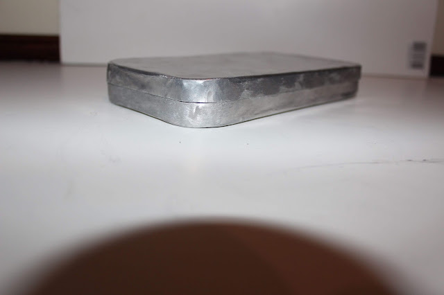
As advised by Russell, i drew contour lines (like those on a topographic map) around the top pattern to determine where to hit to create dip. a technic which was also used in making the bowl.
MY PATTERNS/PIECES:

Fig.11. Top Pattern (spray painted as finishing touch)

Fig.12. Left side
FINISHED PRODUCT:


FINAL PRODUCT (SPRAY PAINTED):


Comments
Post a Comment